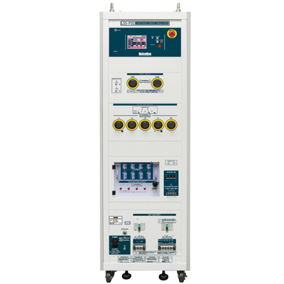
Lightning Surge Simulator LSS-F03 Series new
Conforming to IEC 61000-4-5 Ed. 3 requirements
 Product catalog (1589Kbyte)

MODEL LSS-F03C3
GENERAL
Surges represent transients that might be induced in cables by lightning. By their nature, fairly high energy charges may easily damage or upset unprotected electronics circuits and components. Surges are not a new problem. Many companies have been testing their products at various stages of the products life: design tests, qualification tests, production tests and diagnostic tests.
The advance of surge suppression devices and technique does not lessen the importance of surge testing, but rather increases it, as the requirement to reduce power consumption and to increase the operational speed of semiconductors has become more demanding. In addition, the issue of surge testing is attracting renewed interest since this form of immunity is now a must for almost all electronic products for access to the global market.
FEATURES
- "Output voltage 15kV, current 7500A" which can conduct breakdown resistibility test
- "50% reduction of the output interval" which can drastically reduce the test time
- "Touch-panel" adopted for the easy test setting
- "Multi-languages" for the easy operation processing available
- "Indicator" which is linked with the test setting equipped
- PC control available with the optional software
- "Emergency stop" & "Interlock terminal" which secure the test operator equipped
- "Output waveform monitor terminal" which can ease pre-checking of the waveforms prior to the actual test
SPECIFICATIONS
<Surge Generating Unit>
| Parameter |
Specifications |
Remarks |
|
1.2/50��s-8/20��s
Combination waveforms |
Output voltage 0.5kV to 15kV ��10%
Front time 1.2��s ��30%
Duration 50��s ��20%
Output current 250A to 7500A ��10%
Font time 8��s ��20%
Duration 20��s ��20% |
Common for the all models
Voltage step : 0.1kV step
The setting can be from 0kV |
|
10/700��s-5/320��s
Combination waveforms |
Output voltage 0.5kV to 15kV ��10%
Front time 10��s ��30%
Duration 700��s ��20%
Output current 12.5A to 375A ��10%
Front time 5��s ��20%
Duration 320��s ��20% |
Models: C1/C3
Voltage step : 0.1kV step
The setting can be from 0kV |
| Output polarity |
Positive / Negative |
|
| Interval |
10 sec. to 989 sec., depending on the set voltage 10 sec. (<6kV) |
15 sec. and over in 10/700 ��s waveform |
| Output impedance |
1.2/50��s waveform : 2�� ��10%
10/700��s waveform : 40�� ��10% |
|
<AC/DC CDN>
| Parameter |
Specifications |
Remarks |
| Coupling surge waveform |
1.2/50��s-8/20��s combination waveforms |
|
| Max. coupling surge voltage / current |
Up to the values which can be set |
|
|
Coupling network
Correspondent to IEC61000-4-5 |
18��F: Between LINE - LINE (10�� +9��F selectable) |
|
| 10��: ��9��F Between LINE - PE (18��F selectable) |
|
| Injection mode |
Between LINE - LINE, Between LINE - PE |
|
| Power supply lines structure for EUT |
Single phase AC: L/N/PE
DC : +/-/PE |
Models : A1 / C1 |
|
3-phase AC : L1/L2/L3/N/PE (Common for single phase and 3-phase)
DC : +/-/PE |
Models : A3 / C3 |
| EUT power capacity |
AC240V/20A MAX. 50/60Hz, DC125V/20A MAX |
Models : A1 / C1 |
| AC500V/50A MAX. 50/60Hz. DC125V/50A MAX |
Models : A3 / C3 |
| Decoupling coil |
1.5mH |
|
| Phase angle control |
0 to 360�� ��10�� |
|
<CDN for Telecom lines > (Only in models C1 and C3)
| Parameter |
Specifications |
Remarks |
| Coupling surge waveform |
1.2/50��s-8/20��s combination waveforms
10/700��s-5/320��s combination waveforms |
|
| Max. coupling surge voltage / current |
6kV
(Waveform specifications can be met up to 2kV for 1.2/50��S waveform and up to 4kV for 10/700��s waveform) |
|
| Impedance matching resistors |
40�� |
80�� per 1 line at 2 lines
160�� per 1 line at 4 lines |
1.2/50 ��s waveform |
|
25�� per line |
|
10/700 ��s waveform |
| Coupling mode |
Common mode |
|
| Coupling network |
Gas arrestor : 90V |
|
| Line for EUT |
2 lines / 4 lines DC50V/100mA MAX |
Selectable |
| Decoupling coil |
20mH |
|
<Others>
| Parameter |
Specifications |
Remarks |
| Voltage monitor |
BNC output, 1/2000��10% |
In open-circuit for SURGE OUT |
| Current monitor |
BNC output, 1mV/A��10% |
In short-circuit for SURGE OUT |
| External communication |
RS-232C optical communication |
|
| Power supply |
AC100V to AC240V ��10%, 50Hz / 60Hz |
|
Dimensions |
W555��H1450��D790 mm (Models: A1 / A3) |
Projection excluded |
| W555��H1800��D790 mm (Models: C1 / C3) |
Projection excluded |
| Mass |
Approx. 290kg (Model:A1), Approx. 300kg (Model:A3) |
|
| Approx. 325kg (Model:C1), Approx. 340kg (Model:C3) |
|
SELECTION GUIDE TABLE
|
Model
LSS-F03 |
Output waveform |
AC/DC Power Line CDN |
Telecom Line CDN |
|
1.2/50 ��s
(8/20 ��s) |
10/700 ��s
(5/320 ��s) |
Single phase
AC240V/30A, DC60V/20A |
Single and 3-phase
AC500V/50A, DC60V/20A |
DC50 V 100mA |
| A1 |
Available |
|
Available |
|
|
| A3 |
Available |
|
|
Available |
|
| C1 |
Available |
Available |
Available |
|
Available |
| C3 |
Available |
Available |
|
Available |
Available |
STANDARD ACCESSRIES
| Items |
Specifications/Functions |
Quantity |
Correspondent models |
| Surge output cable |
HOT/COM |
2 pcs. |
A1/A3/C1/C3 |
| Output cable to power supply lines |
For single phase : L / N / PE |
3 pcs. |
A1/C1 |
| For 3-phase : L1 / L2 / L3 / N / PE |
5 pcs. |
A3/C3 |
| Output cable to telecom lines |
For 1 to 4 lines and GND |
5 pcs. |
C1/C3 |
| Arrestor unit |
For coupling : Equipped to main unit panel |
4 pcs. |
C1/C3 |
| For input protection : Equipped to main unit panel |
4 pcs. |
| Cable for monitor |
BNC-BNC cable |
1 pc. |
A1/A3/C1/C3 |
| External interlock connector |
5P plug (Short between #1 - #3) |
1 pc. |
A1/A3/C1/C3 |
| Power supply cable |
For AC100V, 3P equipped with G connector cable |
1 pc. |
A1/A3/C1/C3 |
| High voltage connector cap |
Equipped to main unit panel |
5 pcs. |
A1/C1 |
| 7 pcs. |
A3/C3 |
| FG cable |
For grounding the body |
1 pc |
A1/A3/C1/C3 |
| Instruction manual |
In Japanese/ English |
1 each |
A1/A3/C1/C3 |
Please download LSS-F03 series brochure pdf (1589Kbyte).
LSS-F03 series brochure includes the information on the detailed futures, specifications, optional accessories, the summary of IEC 61000-4-5 ed.3.0 standard, the test set up examples and others.